Here are some suggestions for the best beginners RC and FPV gear in 2025.
I am recommending radios with EdgeTX operating system and ExpressLRS RF link for the best future proofing. This gear will be suitable for beginners and basic models right through to advanced users.
ExpressLRS has now matured enough to be a reliable RC link system with superior range and link security. I would recommend using an ELRS radio with ELRS receivers, then adding an external 4in1 Multiprotocol Module for non-ELRS receivers.
RC Gear
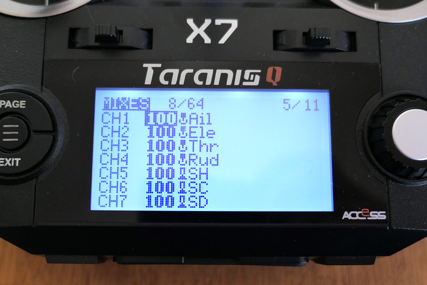
Transmitters

The antenna is fixed but able to rotate and fold away.
The screen is quite small which might be a problem for aging eyes.
Maximum output power of 250mW gives range of several km.

Output power of 1W gives range of tens of km.

Radiomaster ER PWM receiver range
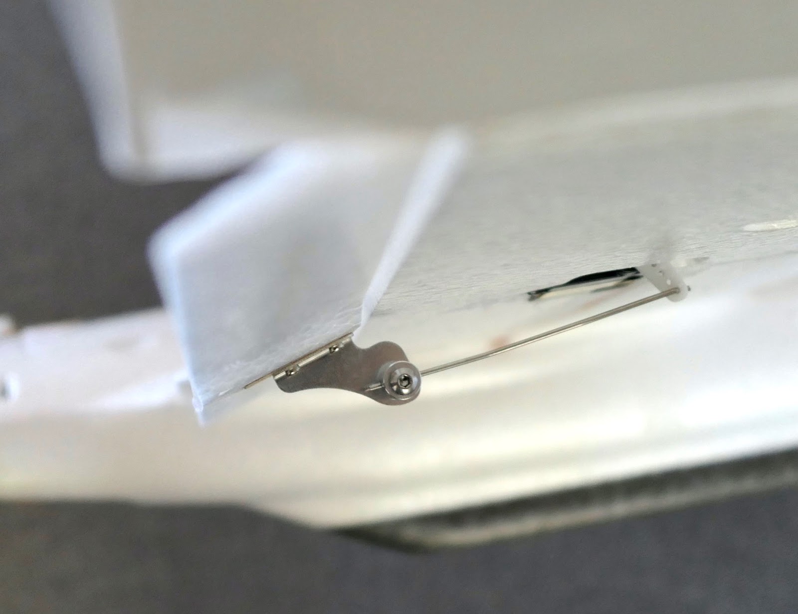
The ER ELRS receivers have PWM pins for each channel and are designed to operate servos directly.
Range of several km is possible with the Pocket and Boxer radios.
4, 6 and 8ch receivers are available, some with a barometer for vario feedback and battery monitoring.
Radiomaster RP serial receiver range

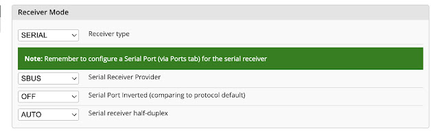
The RP ELRS Serial receivers are designed for use with Flight Control Boards where a serial connection is required.
Serial connection means all 16 channels are sent down one wire.
Analog FPV Gear
The following gear is all standard definition analog because it is much cheaper than Digital HD. It is best to learn FPV using the cheaper analog systems then step up to digital later.
Goggles / Screen
The dual screen goggles like Skyzone or Fatshark are too expensive for beginners and it's best to save your money for future digital goggles purchase.

These are a good compromise between cost and features. The screen can be detached from the goggles and used just as a screen. It has built in DVR recording and dual antennas.
FPV cameras
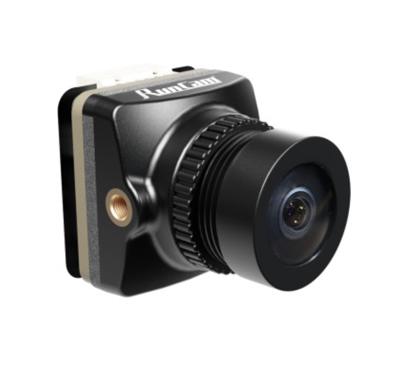
This is my favourite analog FPV camera with 4:3 and 16:9 aspect ratio and great picture quality. The lens has a nice wide angle view.
There are many other camera options and anything similar will work for FPV as long as you pay attention to the required input voltage. Some cameras can only handle 5V and others can handle a wider range.
I prefer 16:9 aspect ratio and a wide angle lens (2.1 - 2.5mm) for use on fixed wing models.
Video Transmitters (VTx)
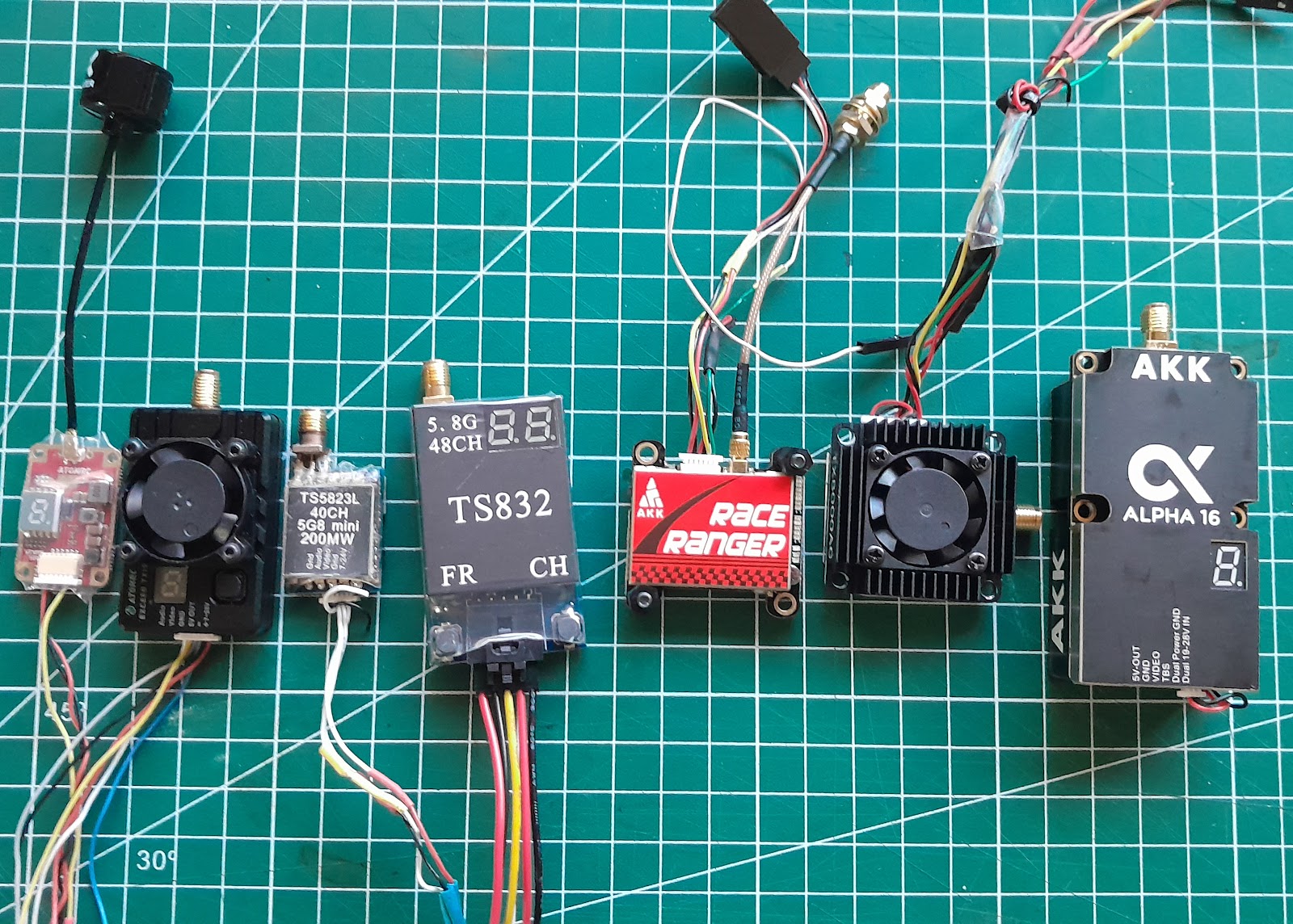
I would avoid the ultra high power VTx. More than 1W power is just not necessary for normal FPV.
Anything with 1W or less is all you need for a few km of range. More range is best achieved with a high mounted directional receiver antenna, rather than pumping out more power.
You may also need to buy an antenna for the VTx. Take note of the antenna connection style such as SMA, RP-SMA, MMCX, uFL.
Here are some suggestions

All-In-One units (AIO)
The cheapest and easiest entry to FPV is to use an AIO camera and VTx
They are not the best quality or range but you just have to supply power (usually 5V) and find the channel in your goggles.
They can also be easily swapped from model to model.
HD video cameras
For high quality onboard video recording here are some great options.

The Thumb cameras are small and light weight but can record excellent video. They don't have an internal battery and require 5V input to operate. This can come from the receiver or another 5V source.
They have a gyro built in and can record a motion data file to be used for Gyroflow stabilised video.
Runcam 2 4k