This is the story of my awesome X UAV One 1800mm wingspan V-Tail sloper.
It was designed to be a pusher FPV cruiser with a unique prop drive mechanism that encircles the boom. However the boom prop gear box was way to noisy and caused vibrations. Bad for stealthy flying and onboard video.
This kit was sent to me by BANGGOOD for review.
While waiting for the motor to arrive I decided to try it as a sloper.
Actually I always intended to reconfigure it for sloping once the review was done.
The poorly designed gearbox really became apparent during my motor maiden flight.
Once that was out of the way it was time to try a tractor motor setup.
Not so good for FPV with the prop in front of the camera, but a much better flight experience.
And finally as a pure sloper with slimmed down fuselage and longer nose,
made from coreplast, hot glue and gaffer tape.
It is now a brilliant sloper that works in light wind, less than 10kn here, and will ballast up nicely for strong winds.
In really strong winds, like 25kn, it was obvious that the single boom V-tail design was still too flexy. So here's the next version.
I doubled the tail boom and changed to a conventional cross tail. At this stage I have no rudder, which works fine for speed runs. If I wanted more aerobatic performance from this glider a rudder would be essential.
I've added balsa fillets at the tail join for a bit more strength.
It's all much stiffer and is working well. So far I have only flown in a 15kn breeze, can't wait for a decent blow.
For the last 2 weeks the wind strength has rarely dropped below 20kn. To keep flying I needed to
design something that could handle strong winds. The obvious candidate was a speedy slope racer.
The balsa-pod version of my Ultralight Sloper was available because it was superseded by the mad-flipping Fusion. Here are the mods needed to transform it into a high wind speedster.
V-Tail 1
Many slope racers use a V-Tail, and I had never tried one, so that was my first mod. I used tape covered 3mm balsa, hot glue and guessed the dimensions. The tail servos are down on the tail, which is not ideal. Not so much for the extra tail weight but the added aero drag.
It flew OK but did not track well at all, drifting and wandering side to side. This prototype V-Tail did not provide enough vertical area.
V-Tail 2
Further reading here suggested that my V angle should be sharper, about 110º and the area needed to be increased.
That improved the tracking heaps but I noticed my tail boom was twisting alarmingly when operating the rudder, as demonstrated in the video below.
Rudder function on a V-Tail is not as effective as a conventional vertical rudder because the control surfaces are acting at an angle to the airflow. Most of the force goes into twisting the tail rather than moving it sideways, and the twist is in the wrong direction, a bit like adverse yaw from the ailerons.
Seems like V-Tails prefer more bank and yank style flying.
V-Tail 3
To increase the stiffness I shortened the tail boom by 150mm, cut 20cm off the 1.5m wing and 30mm off each tail section.
The shorter tail boom and smaller tail reduced the flex nicely resulting in much better speed and tracking.
In strong wind you can add ballast to give more momentum and penetration, which results in more speed. With a 2200mAH Lipo plus an extra 50g in metal washers it could handle 30kn flying crazy fast.
These photos show the final dimensions.
Flying weight with 1300mAH Lipo - 500g
Add ballast to taste
Wing - RG15 160mm chord
XPS foam hot wire cut
Covered with document laminating film
Servos - TGY9018 x 4
Strong wind V-Tail sloper overview and flights
Future design for more speed
For more speed I'll need to increase the tail stiffness further and reduce the drag.
My next high wind sloper design will have two tubes glued together for a stiffer tail boom and a conventional tail for less twisting. With a stiffer tail boom I should be able to place the servos in the fuselage for less drag, and run long push rods to the tail.
Weight is not a problem with these slopers, in fact more weight means more speed.
Ages ago I came across this article by John Gallagher on wax paper bagging DLG tail surfaces, and ever since I have wanted to give it a go.
I'm working on a Fusion style pod and boom sloper designed by Leadfeather on RCGroups and thought bagged balsa tails would suit. My foam elevator is proving to be a bit delicate for repeated rough landings.
2.5mm x 75mm balsa sheet. Elevator will be 100mm wide so an extra strip needs to be glued on.
I'd probably use thinner balsa for DLG tails or sand down the 2.5mm.
Later I realised 100mm wide balsa is also sold at Bunnings.
The 2m Hobby King Phoenix 2000 was designed to be a motor thermal glider, but it works very well as a motor-less slope soarer.
Soren from Denmark, speedsterDEN on YouTube, has some amazing videos of sloping and dynamic soaring with this very cheap glider.
Slope soaring is fairly rough on foam gliders due to the rough and often uncontrolled landings.
The Phoenix has a tough plastic fuselage which is perfect for the job. However the wing and tail need some strengthening mods to help keep it in one piece.
My flap control horns pulled through the foam after a few flights so I added ID card plastic reinforcing to spread the load.
The wing is supplied with bolts and plastic caps to secure to the fuselage. These tore through the thin foam around the rear mounting bolt after a few rough slope landings. I decided to change to a rubber band tie-down mounting method for more durability. The wings were glued and taped together permanently.
I drilled 5mm holes in the fuselage to fit the CF tie-down rods. No reinforcing in this area is needed. The rods are held in place with hot glue.
Here is the wing securely held in place with rubber bands.
Below are videos explaining these mods and showing some flights.
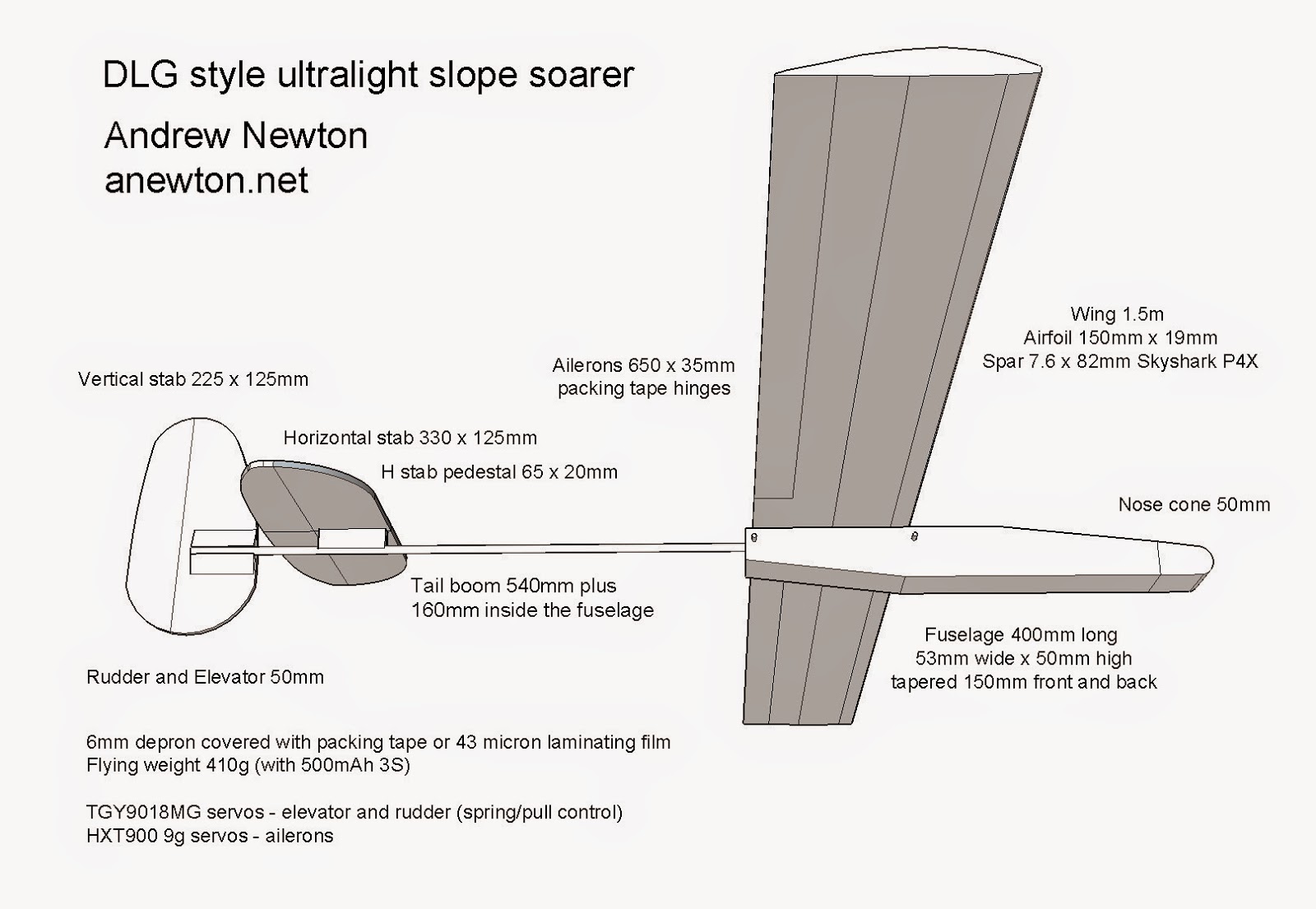
The design for this lightweight aerobatic slope soarer was inspired by DLGs or discus launch gliders.
It will work in anything over 5kn on a decent slope and in 10kn it will work on any slope.
The rudder and elevator are operated by a pull line acting against a torsion spring.
This unique system means the servos can be forward in the fuselage and there are no pushrods going to the tail.
The trick is to make a torsion spring strong enough to operate the control surface against the airflow
but not so strong as to overpower the servo.
The 0.4mm SS wire provided as pushrods for the Versus DLG turns out to be perfect.
UPDATE March 2015: On really hot days the rudder and elevator servos have moved out of position as the glue softened. I have added more foam packing and glue to fix them securely. The trailing edge of the wing has also popped open twice. I removed the ailerons, re-glued then taped the join, then reattached the ailerons. In the original build, by cutting out the ailerons from the wing, I removed too much of the glue holding that join.
This twin boom pusher is similar to the 1.3m Depron Spectre, however it has a straight 1.65m (65") x 190mm depron Armin wing and twin rudders.
1.3m Depron Spectre and 1.65m Twin Boom pusher
Initially it was designed it as a 1.8m light-wind slope soarer but didn't perform as well as I wanted. The longer tail booms and larger wing span made it too flexy and delicate. I was also comparing the performance to a motorless Phoenix 2000, which is a sensational sloper.
Shortened tail booms and wingspan stiffened up the airframe nicely and the addition of a motor fuselage turned it into an excellent FPV cruiser and medium wind FPV sloper. It tracks well in a straight line and has a decent glide angle but is quite agile like the Spectre.
Instead of using packing tape to cover the depron I used document laminating film, often referred to as New Stuff in the RC world. It is ironed on with a warm iron before bending the airfoil and fuselage, and works very well. It's tougher and easier to apply than packing tape.
Additional strengthening ...
6x1mm CF strip glued along the front of the elevator.
Heat bent UPVC brackets for the rudder to elevator joins.
I used twin rudder servos rather than one servo and a long vulnerable connecting pushrod between the rudders. Full length wing spar made from 2 Skyshark P4X spars joined with an internal CF rod joiner and epoxy.
Everyone has heard about the 2m Radian. It's a very simple no-aileron motor glider with graceful curved up wings and has fantastic thermalling abilities.
For A$200 the "Plug and Play" version comes with a good quality motor and servos fitted and not a lot of assembly required. Add your own receiver, battery and transmitter.
I bought mine from RCWorld in Geelong. They have all the spares too.
Like all planes there are a few issues to be sorted out before flying. It is very light and flexy, especially in the tail area, and some of the fittings are inadequate. Most owners carry out strengthening mods and Paul Naton, well known glider tutorial DVD producer, has published a mod video which is essential viewing. Paul Naton's Radian mod video Essential mods needed before the first flight
Pathetic plastic clevis connectors
The pin on mine broke just trying to clip on to the control horn the very first time! What were Parkzone thinking? These ridiculously weak plastic clevis connectors are just wrong. May be OK for a tiny indoor foamie but not a 2m thermal glider.
I couldn't find another connector to fit the pushrod thread so decided to beef up the existing one with a piano wire pin. Just needed to carefully drill holes in the cheeks using a piece of the wire as a drill bit. Tight fitting shrink wrap (not shrunk) keeps the pin in place and connector cheeks pulled in.
Staples into foam?
What is the purpose of these staples? They were straddling the pushrods where some sort of fixing structure should have been. I pulled them out, they were already floating loose, and threw them away because they offended me!
My solution was to use tough clear gaffer tape to fix the pushrods securely to the fuselage leading into the rudder and elevator.
Missing canopy magnet
The canopy is held in place by magnets front and rear. Unfortunately one of the fuselage magnets was missing. Luckily I had a replacement in my spares box and I glued it in with gorilla glue.
Changed ESC connector
The Parkzone ESC comes with an unfamiliar (to me) blue connector, to match Parkzone batteries I guess. All my LiPos have XT60 connectors so a little soldering was required to swap the ESC to XT60.
Receiver bay surgery
The receiver bay is made for a small Spektrum Rx but all I had was a bulky 8ch Turnigy Rx. All I had to do was cut out a little mound of foam to make it fit.
After those easy repairs/mods it was airworthy and ready for the maiden flight. The day was windier than ideal but the Radian performed superbly. No thermalling on the first day but on subsequent days I climbed to frightening heights, lots to learn.
I had previously checked the range of my Turnigy 9X transmitter with a 6ch Hobby King receiver. I got more than 800m at low altitude flying along coastal dunes. The highest I have had the Radian is 300m, and I wouldn't want to go too much higher at this stage, so it would have no problems with signal strength. At 800m the glider would not be visible anyway.
Optional performance mods - (inspired by Paul Naton)
Elevator control horn placement
The control horn was relocated inwards about 12mm to give the pushrod a straighter run. The control horn base was shaved off where it now overhangs the elevator. Elevator was stiffened along it's span using 12k carbon tow and epoxy.
Elevator hinge was taped both sides with clear packing tape for durability. Moulded foam hinges will fail eventually, they are not designed to last. Fixed the horizontal stab in its slot with clear gaffer tape both sides, above and below.
Fuselage stiffening
Added 3 strands of 12k carbon tow along the bottom of the fuselage boom to reduce tail flex. I covered that with clear packing tape for smoothness.
Wing slot top strengthening
I added 3 strands of 12k carbon tow over the top of the wing slot because this area is quite thin and prone to failure.
Wing leading edge tape
After a few flights I noticed that the leading edge was becoming dented and scratched so I added clear packing tape back to 50mm from the LE top and bottom
Wing retaining velcro / magnets
There are many horror stories on the forums about wings falling out in flight. They are very weakly held in with friction and slightly keyed foam blocks that do nothing at all.
Initially I used sticky back velcro on all the meeting surfaces of the two wing halves but that pushed the wings apart by almost 1cm. My current solution is magnets glued to 40mm dowel inserts. These are quite securely glued into the wing roots with epoxy also strengthening that area nicely.
Rudder root strengthening
To stiffen the area at the base of the rudder I cut a slot and glued in a 6x1mm carbon strip pushing it right down into the foam of the fuselage.
Decalage mod
All of these stiffening mods add a little tail weight moving the CG rearward. This is actually a good thing according to the experts. The stock CG of 70mm is too far forward requiring up elevator to fly level. The Radian is designed with lots of horizontal stabiliser decalage angle as seen below and performance can be improved by moving the CG back and reducing the decalage angle. Well that's the much-debated theory anyway.
I tried the decalage mod by slicing out the foam wedge (marked below) and repositioning the horizontal stab. At this early stage of my thermal gliding journey it felt like too much and I couldn't get it to fly smoothly. So I have gone halfway back. Seems like a good compromise now with my CG at 78mm or 3".
Painted bottom surface of the wing
For visibility and orientation. This glider starts to be difficult to see higher than 300m. Solid black seems to be the most visible colour at that distance.
Radian videos
Trying different camera mounting spots
Thermal flight in Google Earth, recorded with a GPS watch
Slope Soaring
and finally Stormy loves the box so all is good.
UPDATE: I left customer feedback on the Horizon Hobby site about the broken clevis connector and missing magnet and they sent me replacement pushrods and canopy, posted in two separate parcels from US to Australia. Now that is awesome customer service.
Here's a demo video covering how I add dihedral to a depron Armin wing.
I show how to bend a 200mm length of ali tube to set the dihedral angle and hold the spars.
This video also shows my swappable motor mount for the Red Sloper and other construction tips.
Here's a slope soaring video showing how the dihedral makes the Red Sloper into a smooth and relaxing glider while slightly reducing the aerobatic capability.
I have never tried a 3 channel rudder elevator throttle plane so thought I'd give it a go using the orange slim wing and pusher fuselage.
RET planes need some wing dihedral to enable turns due to the lack of ailerons.
I fixed the ailerons in place and removed the servos. This simplifies the plane greatly, the wing is just a wing, no servos or wires, apart from rudder and elevator.
The CF spar was removed and a bent 200mm x 10mm diam ali tube inserted to set the dihedral. The wing extensions were hot glued in place at the desired polyhedral angle. The wing seems to be strong enough without a CF spar.
I increased the rudder area, but after the maiden reduced the throws for smoother control.
The 1500mm x 200mm wing and flying weight of 630g gives a wing loading of about 21 g/sq dm (7oz/sq ft) which is great for gliding and slow flying.
This plane is a delight to fly, so slow and steady. If I had started with something like this the learning process would have been much quicker. I can trim it to fly hands off in big lazy circles and it takes care of itself.
Before the Red Sloper came this 2m wingspan sloper. It actually started life as a motor glider but a dodgy ESC connector stopped that project from being fully realised. I'll revisit it soon.
I call this one the Albatross for obvious reasons.
The orange plane is the pusher trainer with a 1.5m polyhedral no-aileron wing adapted from the slim wing. I'll post about that one when we get a nice calm day to do a proper maiden.
The depron I use comes in 1000mm x 700mm sheets so I can make the 2m wing in 2 halves.
I used 3 Skyshark spars all up, 2 joined with a 10mm x 150mm ali tube for the main spar and another spanning the join closer to the leading edge. The spar layout is visible in this shot of the wing on an earlier version of the fuselage.
The wing has full span ailerons operated by TGY 9018MG metal gear micro servos. Total chord is 200mm including the 35mm ailerons. That gives a 10:1 aspect ratio.
I suspect 40 to 45mm ailerons would have been better to give a faster roll rate for some aerobatics but they are fine for smooth cruising.
Airfoil thickness is 23mm, formed by using a 3mm strip of depron over the main spar, giving an 11.5% airfoil.
The tail is just a little scaled up from the Red Sloper but basically the same shape.
Horizonal stab is 460mm wide x 90mm deep tapered to 70mm at the ends plus a 50mm elevator.
Vertical stab is 220mm high x 130mm at the base tapered to 60mm at the top plus a 50mm rudder.
Elevator servo, hidden inside the fuselage, is a TGY 9018MG and rudder servo is HXT 900.
Fuselage is a 1000mm long x 70mm square tube tapered towards both ends for looks, weight saving and aerodynamics.
Weight is 650g without battery and balance weights and 830g flying weight.
The big wing makes for an excellent light wind slope soarer which also works well in strong winds. It's smooth and languid in the air, not so aerobatic, but a delight to cruise along the ridge.
UPDATE: I made the nose removable so I could swap to a motor pod. Just have to pull off the tape around the join and re-tape the motor pod on. The motor glider version is 730g without battery and 925g flying weight.
It took some decalage adjustment to smooth out the tendency to loop up under power. I needed to tilt the wing forward by sticking about 8mm of packing under the rear mounting area. Then it tracked level and glided much better.
Here are the specs for the Red Sloper fuselage, designed and built especially for the 1.5m depron 10% chord wing detailed in the previous post.
Aileron servos - TGY 9018MG metal gear micros
Elevator and rudder servos - HXT900 9g
Receiver - Hobby King 6ch
BEC - Hobby King 5A
The 750mm fuselage is a square tube 50 x 50mm outer size constructed using Flite Test style joins rather than ExAir style bends.
A 15mm x 350mm tapered slice is removed from each side, and the bottom bent up and re-glued to close the gap. That gives the tapered rear half.
Horizontal stabiliser is 440mm x 130mm, tapered to 100mm at the ends, and the 50mm elevator is cut from that.
Vertical stabiliser is 200mm high, 120mm at the base (for a longer glue join) tapered to 40mm at the top. Rudder is 50mm tapering to 20mm at the top.
The control surface tapers are just for looks, but looks are very important. A daggy tail ruins the overall impression of the plane.
Elevator servo is stuck inside the fuselage near the rudder servo.
There is no need to have the tail servos mounted forward with long push rods. The amount of weight saving is not significant for a speedy slope soarer. In my normal 10-15kn flying conditions more weight is often needed.
The nose is soft EPP foam with a tongue extending into the fuselage. It holds the battery, nose weight (4 large washers), BEC and receiver.
Nose is held on with 2 velcro tabs.
Wing tie-downs are 4mm carbon tubes glued in and reinforced with ID card plastic
Here's the maiden flight of this excellent glider, probably my best design and build so far.