
DLGs are highly refined, super light and stiff hand launched gliders. You launch the glider high into the air using a discus style spin and fling, then go hunting for thermals.
Have a look at David Windestal's brilliant DLG video with lots of unique camera angles, and this slow mo one too. Maybe you will see why I'm hooked.
Competition level carbon fibre DLGs can cost up to $1000, but the entry level Versus DLG kit from Hobby King is much more affordable at around $200.
Versus DLG kit

The kit doesn't include servos. Four good quality 5g micros are required so I went with the recommended Dymond D47. They're expensive at $30 each but tiny and powerful.
DLGs benefit from very light and accurate servos. Some flight modes require control surface deflections of 1.5mm or so. Cheap servos just can't do that repeatedly.
UPDATE 8th Dec 2013 - both aileron servos have stripped gears after 2 separate rough landings. Looking for tougher metal gear micros as replacements. Folks on the forums say D47s are not suitable for ailerons but OK for rudder and elevator.
Download the build manual pdf from the International HK site under "Files". It's OK but lacking in important details. Build logs are available here for the similar Topsky and here for the Versus.
This MEGA discussion on RCGroups covers every aspect of the Versus DLG. 53 pages and counting but definitely worth skimming through.
Important tips picked up from that discussion...
1. Don't hold your finished Versus out horizontal by the wing tip, it may fold.
2. The tail boom in the kit is too long and needs to be cut down. More on that later.
The kit includes the fibreglass covered foam / carbon fibre wings, fibreglass covered balsa tail pieces, fibreglass body, carbon fibre tail boom and an accessories pack.

My accessories pack was a bit random with an extra servo mount, 2 finger pegs and tabs but no balsa piece to mount the horizontal stabiliser.
The supplied tail boom is 700mm long but the plan has it at 650mm. The general consensus on RCGroups (and Hobby King support) is that 700mm is too long. You need to cut the boom to 650mm or less, otherwise you will need lots more weight on the nose to get the CG right. Cut the tail end not the pod end or you will never fit them together.
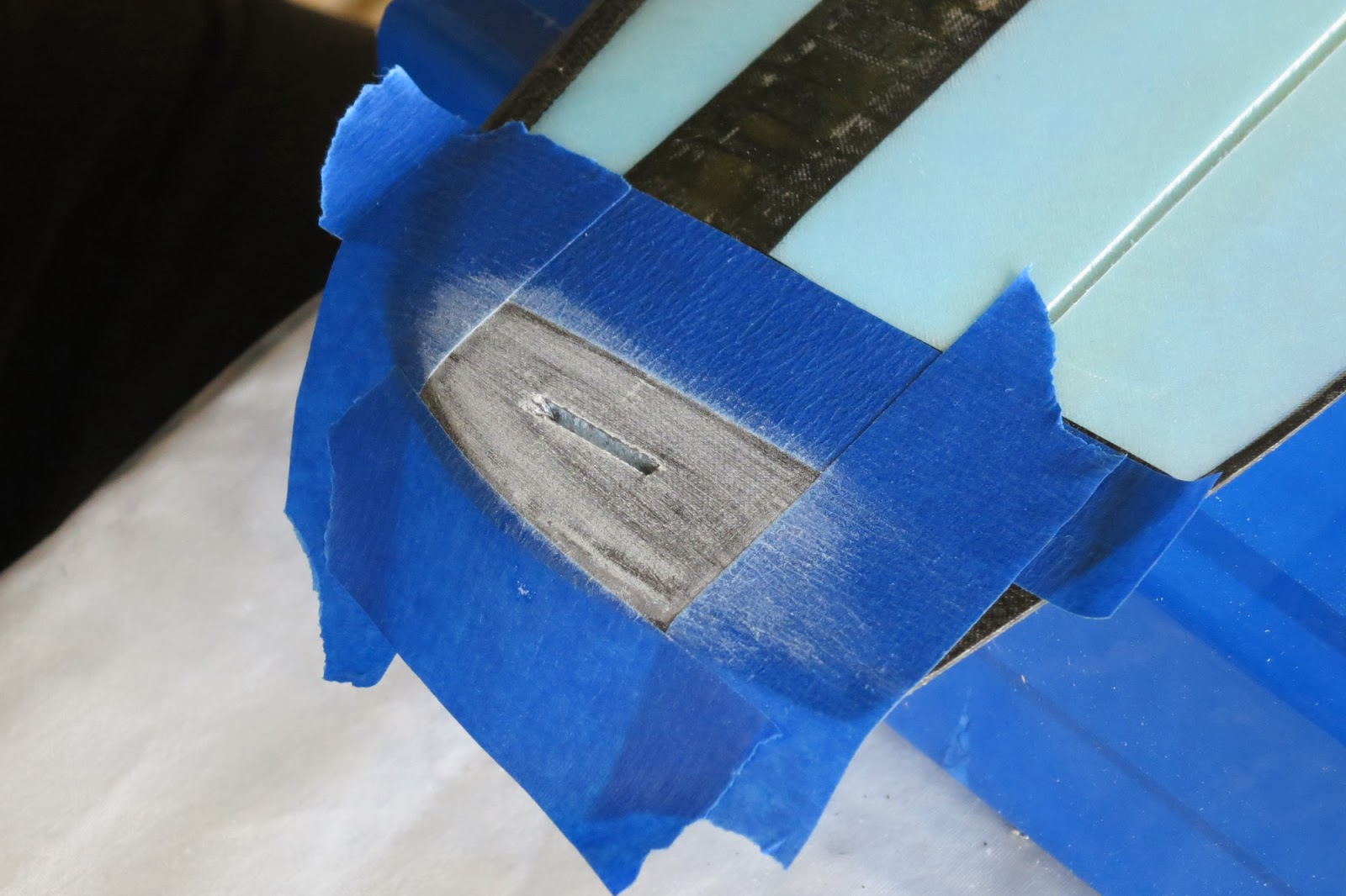
Wing attachment hard points

Step one is to gouge out the foam around the wing bolt holes to create hard points.

Make a 10mm deep and 25mm wide rectangular space centred around each half bolt hole

Fill with an epoxy resin and micro balloon mix. Micro balloons make the mix lighter, thicker and easier to sand. There are alternatives like Talcum powder which work just as well. I actually used micro fibres and West Systems 105 epoxy because that's what I had. Might be marginally heavier.

Let it cure overnight then sand down the raised areas so the wings fit together nicely.
Re-form the half bolt holes with a round file
Wing servos

The aileron servos mount into the underneath surface of the wing below the square carbon fibre patches. The manual shows the servo butting right up to the carbon fibre spar ribbon but that means you must cut into the ribbon to get full throws of the servo arm.
I moved my servos forward 5mm.
I moved my servos forward 5mm.

Use a sharp knife to cut through the fibreglass

Mill out the foam to the correct depth for your servo using a dremel
or carefully pick out the foam with some sort of pick.

Bore a hole through from the wing root for the servo lead. I used a drill bit by hand
Joining the wings

Tape the wings together along the undersurface using masking tape then turn the wing right way up. Glue the two wing halves together using epoxy glue (I used 5min Araldite) being careful not to fill the servo lead holes and bolt holes.

With one half of the wing weighted down lift the other tip up to 162mm to set the correct dihedral.

Support the lifted wing with something underneath making sure the join doesn't move out of alignment and let the glue cure. Once the glue has cured you can pick up and admire your full wing. Starting to look like a real glider now.
CF cloth reinforcing

Roughen up the top of the wing join with sandpaper to a width of
25mm then mask off with masking tape.

Cut two pieces of carbon fibre cloth to 25mm x 185mm. A roller cutter works well for this.
Mix up a small quantity of Epoxy finishing resin and paint some sparingly over the wing join.

Lay one piece of CF cloth onto the join and paint with more resin.
Use as little as possible just to make the cloth uniformly wet.

Blot up the excess with paper towel.
Lay some light plastic over the wet cloth to give a smooth finish when cured.

When the resin has cured re-form the bolt holes
by drilling through the CF cloth.

Reinforce the under side of the wing join following the same method.
When cured open up the bolt holes again by drilling.

Pick up your wing, marvel at your achievement and photograph it's gorgeousness (Optional)
Servos and control horns

The kit comes with a 4 pin connector but it was too small and fiddly for me to deal with so I opted to just extend the 2 servo leads to the receiver.
Cut the plugs off the servo leads and extension leads.
Cut the plugs off the servo leads and extension leads.

Thread servo extension leads through the holes and solder on to the servo leads
Make sure your extensions are long enough to reach the receiver. I used 150mm extensions.
Dont glue the servos down just yet.

Mark the control horn position on the aileron. The slot should start a few mm back from the hinge line to prevent the control horn poking through into the hinge gap.

Cut through the fibreglass with a knife to create the slot
and glue the control horn into position.
and glue the control horn into position.
Aileron / Flaperon Push Rods

Cut 2 x 30mm pieces of the thin wire and make small z bends.
Glue them to the CF push rods with epoxy.
I used heat shrink tube as well to hold them in place.

Use a servo tester or your transmitter / receiver to centre the servo arms.

First make sure the clevis fits on the CF push rod. I needed to enlarge the hole to make it fit. Drill out the end servo arm hole so the clevis pin fits through with no slop. Carefully mark and cut the CF rod to the correct length. Fit the clevis and attach to the servo arm.
I made the wire z bend on the flaperon end of the push rod because it fit perfectly in the existing control horn with no slop whereas it was too loose in the existing servo arm hole

Slide the clevis along the push rod until there is zero flaperon deflection with the servo arm centred. Drop on some CA glue to fix the clevis in position on the push rod.
Finger tab and tail control horns

My kit seemed to provide the choice of finger peg or finger tab. They both weighed the same so I went with the tab which would give less drag. Using a knife I cut the slot about 15mm in from the end and slightly overlapping the line of the CF ribbon spar as in the Versus manual.
Mask around the slot top and bottom, roughen with sandpaper.

Not enough leftover cloth in my kit to use single pieces so I cut a few smaller patches to cover the area.

Once cured and sanded reopen the slot and glue the finger tab in.
I used plenty of thickened 30min epoxy. This area needs to be strong.

Make sure the tab is vertical and aligned with the centre line.
Rudder and Elevator servos

Fit the servos into the plywood mount. The Dymond D47 screws are pretty chunky so I used some smaller 9g servo screws. You need to remove one servo to get it all inside the pod.

My servo mount was too narrow and didn't reach to the pod walls
so I glued in 2 balsa supports for it to sit on.
so I glued in 2 balsa supports for it to sit on.

Checking to see how all the bits fit in. You need a small battery to fit into the nose. Turnigy Nano tech 300mah 2C is a good fit but maybe not heavy enough. We shall see.

The Hobby King 6ch receiver is a little too big to fit so I removed the case
and replaced it with 25mm heat shrink. It fits easily now.
and replaced it with 25mm heat shrink. It fits easily now.
Boom length and tail pieces

Open the preformed slots in the tail pieces with a knife and glue the control horns in place.
They go on the opposite side to the kevlar hinge tape.

The tail boom is too long at 700mm. Recommended length is 650mm or less.
I chose to cut off 60mm giving 640mm. Cut from the narrow end not the wider pod end.

Cut slots in the end of the tail boom to fit the vertical stabiliser

Glue with epoxy using as little as possible. Any excess weight in the tail area should be avoided. Make sure the tail is vertical and perfectly aligned with the centre of the boom

Glue 2 blocks of balsa together to form the horizontal stabiliser mount.
Size is 25mm front to back, 20mm high and 10mm thick

Shape it into a nice airfoil shape to reduce drag. Wrap sandpaper around the boom to shape the concave bottom surface so it fits snugly on the boom

Mark the centre line of the horizontal stabiliser

Tape it down flat and aligned with the lines running across a cutting mat

Now take a deep breath and relax. This part needs accuracy.
Glue the mount and boom on using 5 min epoxy
1. Vertical stabiliser must be at 90º to the horizontal stabiliser
2. Boom must be at 90º to the horizontal stabiliser.
Use the lines on the cutting board for reference
3. Height of the boom centre line must be the same at both ends.
I used pieces of foam board to support the boom at the right height.
There is a bit of debate on the forums about whether you should align the horizontal stabiliser with the top, bottom or centre of the boom. There doesn't seem to be a definite answer so I went with the centre. Seems logical to me.

If all that went well your tail section should look like this. Now to reinforce those joins with the supplied fibreglass cloth and epoxy finishing resin.

Cut fibreglass patches to cover either side of the rudder join and a longer piece to wrap around the boom and up either side of the elevator mount.
This fabric roller cutter works beautifully.

Paint resin on the joins then position the fibreglass cloth.

The manual says to spray with adhesive first but I find it too messy
and it makes repositioning the cloth difficult.

Wet out the cloth with more resin, sparingly of course.
Dab with the brush to remove any air bubbles
Spring / Pull tail hinges
I decided to try spring / pull control for the rudder and elevator. Main reason being I couldn't work out how to use the push rod and casing provided in the kit. The teflon casing is meant to run down the outside of the boom. I thought this looked ugly and drag inducing and I couldn't get the teflon to glue successfully. The spring / pull setup is an elegant solution and saves tail weight.
Drill angled holes for the pull string to exit from the boom

Glue in some plastic tubing for the string to run through


Using the 0.4mm push rod wire from the kit bend up 2 staple-shaped torsion springs.
Legs 25mm and middle 50mm

One leg is inserted into the balsa of the rudder and the other leg is inserted into the balsa of the vertical stab. Same for the elevator and horizontal stab.
This part is quite tricky.The wire wants to break out through the fibreglass as you push it in.
I ended up drilling holes and feeling with fingers on each side whether the drill was threatening to break through. I inserted some of the teflon tubing then inserted the wire legs.

The elevator hinge kept popping out so I had to glue the legs in the teflon tube and strengthened the surrounding area with CA glue.

Here it is all connected. Seems to be a fair force on the spring, hope the servos are up to it.
Final gluing, assembly and adjustments

To secure the wing servos they were wrapped in masking tape then glued in with 5 min epoxy. The idea is that I can remove, replace or reuse them if needed.

I had to remove the spring / pull lines to glue the pod to the tail boom

Making sure wing and horizontal stab are perfectly aligned

Final adjustment of the refitted spring / pull linkage.
I changed to a thinner kevlar line and 2:1 purchase loop to allow finer adjustment. Very fiddly trying to tie knots so the rudder and elevator are centred. No doubt I'll try different methods of fine adjustment, this one is not as clean as I'd like.

Checking the CG. The manual says 70 - 80mm back from the leading edge. Mine was about 90mm back unweighted. 15g extra in the nose brought it to 75mm.

Finished weight 275g or 290g balanced correctly. Now how do you fly these things?
Here's the narrated build video
Excellent build notes! I've read a couple of build logs for this and the TopSky DLGs, but most of them make the assumption you've done this kind of thing before. Ummm... I haven't done this kind of thing before! So thank you for the step-by-step notes.
ReplyDeleteGlad to see someone else is using West System. I've got gobs of colloidal filler left over from refurbishing my boat. It's good to know I can use that instead of microballoons. If (ok ok... WHEN) I jump into DLGs, I'm likely to go that route.
Eager for the next installment!
Thanks Tom. I'm really enjoying the journey.
DeleteI couldn't find the level of build detail I wanted either. Definitely have to make the parts fit rather than assuming they are designed properly. More of an actual build rather than a "Click together" kit but the parts are all really good quality.
The shed calls….
just got mine yesterday. going to build over the holidays. thanks for the build guides! let you know how it goes.
ReplyDeleteExcellent. Feel free to ask if you have any queries. What servos are using?
Deletewill buy tx/rx and servos next month....hobby shop around here has futaba/ jr, etc......any recommendations?
DeleteYou need at least 5 channel and programmable. I haven't used Futaba, JR or Spectrum but they are well respected. I went the cheap route and bought a Turnigy 9X, then loaded the openTX firmware using a Smartieparts board.
DeleteServos in the pod (elevator and rudder) need to be small enough to fit and strong enough to resist the constant spring tension (if you opt for the spring pull) $30 Dymond D47s in mine are working well here but might use D60s in the next one.
Aileron servos need to be small, strong AND tough. My D47s didn't last long in the wing. Stripped gears after a few hard landings. Now using $4 HXT500s just taped in and they seem to be fine for the moment.
how again did you choose to do your control cables? I tried 10 cm x 10 cm balsa, and attaching control cable tubing to that....but am still getting a lot of binding. i do not quite understand the spring setup. perhaps i haven't paid enough attention, but it seems foggy. after your experience how would you handle the rudder/elevator control cables?
Deletesorry, i did not specify before in the above post. elevator and rudder cables. what type of system would you recommend. i have noticed that the stock ones tended to bend/bind/bow. what about a pull/pull system?
Deleteended up going with pull/pull using nylon string. i worried about the constant tension on the servos from the spring draining the batteries. i hope this works
ReplyDeleteFair enough, let us know how it goes. I've used pull/pull for steering on an RC land yacht but not for planes. Need to keep tightening the line to avoid slack. As for draining batteries, my little 300mAh 2C is only half drained after 1.5hrs of constant launching and flying. I'm knackered by then so it has never been an issue.
Deletewhile i am waiting for next month to come to buy my tx/rx/servos, i ran across some VERY light and strong (10lb+) fishing line. replaced bulkier/ heavier nylon with that. very smooth operation.....
Deleteyou mentioned you had to add "x"g of nose weight to get the CG proper. is there any way to slide the rx, servos, and battery further forward? (even if having to make separate servo mounts, etc?) i'd like to minimise the amxt of weight having to be added for proper cg.
DeleteYou're not alone there. Moving everything as far forward as possible is essential. But you still need to get the battery and BEC out. The most important thing is to minimise the weight at the tail.
Deleteservos now mounted in wing...went with hitec micros...8g each ball bearing carbonite gears, so hopefully they'll survive. getting ready to go get my rx/tx today....maiden flight tomorrow?!
Deletei love this sailplane. i used to r/c 20 years ago. i built many kits, had many cool planes. this by far is my favourite thus far. i can fly this nearly anywhere. i ended up on the high end of weight, though, due to my local hobby shop's limited supply of rx batteries. i got the smallest they had, ...had to re-solder the batteries to a proper order to fit in the nose cone. 310 grams, ready to fly. my servos were 8 g each i just rebuilt my vert/horizontal stabs due to a couple of mishaps. (did i mention i would chuck this in the grocery store parking lot whilst grocery shopping? :) ready to start looking for the next step up in dlg. i am hooked
ReplyDeleteI've learned that the right weight and CG for the conditions is more important than minimum weight. I put an extra battery in for weight recently because I was struggling to keep control on a windy session. Total transformation, flew better than ever.
ReplyDeletewhat's your flying weight for windy conditions? mine was getting tossed around a bit in the breeze yesterday
DeleteIt would have been about 320g. Only tried it once.
Deleteack! be sure your rx is on before launching!!!! wing at least broke at the center joint....time to rebuild.
DeleteOh no! Hope it's repairable.
Deleteeasy repairs! tough and lightweight!
DeleteGreat job. I have just gon and brought one of these. I dont know where but somewhere I read that the glider needed 9g servos, so I went and brought 4x 9g metal gear servos from hobbyking. Will these be ok, or will they be too heavy.
ReplyDeleteCheers
Johnno
5g servos is the reccomendation but it's not so much the weight but the size. The issue might be fitting two side by side in the pod. That's where the tiny Dymond D47 are good, and they have enough torque to resist the Spring/Pull setup. For the ailerons micro metal gears are a good idea. I have stripped 2 D47s and 2 HXT500 servos in rough landings.
Delete