This information is correct up to INAV V2.6
FAQs and common problems
 Which firmware target to flash?
Printed on the bottom of most Matek boards or on the product page
Servo throws are too small in stabilised modes?
Increase FF values in PID Tuning page
Not holding altitude in Angle Mode?
Increase Pitch Degrees in Configuration Page (or Mechanics tab of the PID page for INAV 3, 4 and 5)
Flying too slow in Altitude Hold and RTH modes?
Increase Cruise Throttle value in Advanced Tuning page
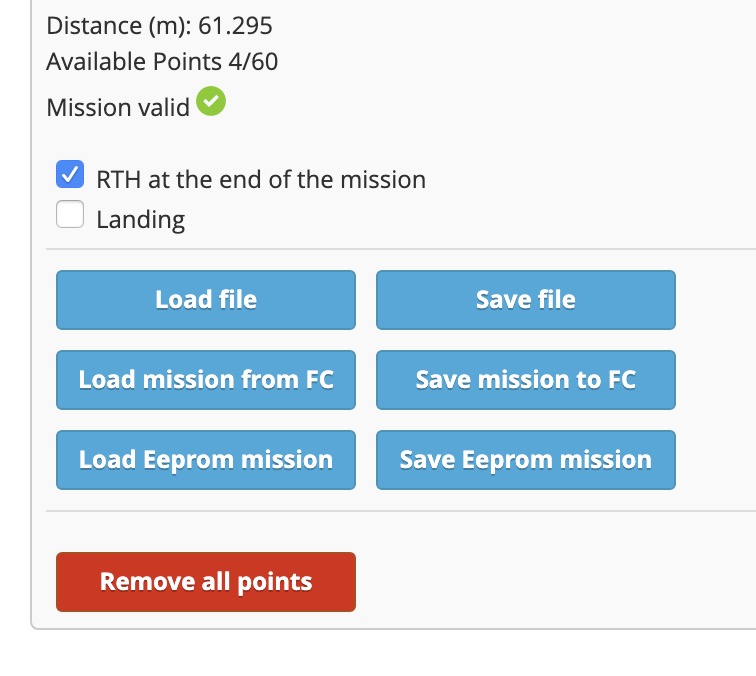
Will failsafe work if signal is lost?
Turn off the transmitter and check that the little parachute turns red in the INAV configurator
GPS not working?
Switch Rx and Tx connections
Servo reversed?
Select reverse for that servo in the INAV configurator Outputs page
Stabilisation reversed?
Invert the Channel in your transmitter.
Check that the board is facing the right way. Arrow pointing forward.
How to use Autotrim?
Fly in Manual Mode, activate Autotrim and fly level for 2 seconds, keep autotrim on, land and disarm. Repeat whenever you need to retrim.
How to use Autotune?
Fly in Acro Mode, activate Autotune and fly around for a few minutes making full deflection roll and pitch changes. Turn Autotune off in the air. Land and disarm. Save the new PIFFs by pulling both sticks down and out.
Stick Commands don't work?
May be prevented by a Throttle Cut switch or lack of Yaw channel on a flying wing.
Elevator, Aileron, Throttle and Rudder channels must be active but the board disarmed.
Introduction to INAVFlight for fixed wing
 INAVFlight is Open Source firmware for flight control boards, which enables GPS navigation for planes and flying wings, as well as multi rotors.
It is an independent project developed by hobbyists and hosted on Github. The developers are not paid, they do this purely as a hobby. So that means any changes happen because a developer feels like it, or enough users have asked and a developer agrees or has the time to write the code.
INAV is quite amazing, powerful, confusing, messy and hard to understand initially, but really worth making the effort to learn.
Before connecting a flight control board
First concept to understand is that INAV cannot work well with a plane that is out of trim.
Centre of Gravity, Aileron and Elevator throws, and trims must be sorted first without using the transmitter trims and rates. Adjust the pushrod lengths and connection holes as much as possible so the plane is easily controllable and correctly trimmed for level flight.
INAV Configurator
 This is the computer program used to load and configure INAV firmware on your flight control board.
Note that this is not the INAV Firmware just the INAV Configurator.
USB drivers
Before you can connect a flight control board (FCB) to your computer you may need to install the correct USB drivers.
 Links to the required drivers can be found on the INAV
 Configurator front page.
Download and install the relevant USB driver for your computer.
Open INAV configurator and connect your board via USB. Be careful with the delicate USB socket on your board. I usually add some epoxy glue around the base of the socket.
Select the correct port for your board. It should show up in the list when the board is plugged in. This shows the port used on my iMac.
Now click Connect.
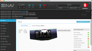 If the INAV firmware version and INAV configurator version are compatible then this is what you will see.
Otherwise you will get a message about what needs to be updated. You may need to update to a more recent INAV configurator or flash the board with more recent firmware.
Flashing new firmware to the flight control board
To flash new firmware the board needs to be in DFU mode. Matek boards, and most others, have a boot button. Hold down the boot button and reconnect the USB cable, then release the boot button. DFU should show in the port window.
Or just type DFU in the CLI while plugged in.
Now click on Firmware Flasher.
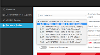 Select the correct target for your board. The target
 may be written on the bottom of your board or on the product page.
Dont just guess, the target names are not always obvious. For example the Matek F405-Wing board needs the MATEKF405SE target.
Select the firmware version from the list
Click Load Firmware (Online).
Or Load Firmware (Offline) if you have the firmware file saved locally.
Click Flash Firmware
If all is working you will see the progress bar start moving. Once it's done the board will be updated and ready to configure.
If not you may need to try a more recent computer or ask for help on the INAV forums. I cant flash firmware with my 9yo MacBook but my 3yo iMac works fine.
Model setup in your transmitter
Another very important concept to understand is that you don't use any mixing in your transmitter, all the mixing work is handled by INAV and the flight control board. All you need is 100% weight on the first 4 channels for the sticks, and whatever mode switches you need. This model setup can be used for all INAV craft including airplanes, flying wings and multi rotors.
Here is my setup
Ch1 100 Ail
Ch2 100 Ele
Ch3 100 Thr
Ch4 100 Rud
Ch5 Nothing / Arm (2 pos switch)
Ch6 Nothing / Angle (2 pos switch)
Ch7 Nothing / Cruise / Position Hold (3 pos switch)
Ch8 Nothing / Manual / RTH (3 pos switch)
Ch9 Nothing / Auto tune (2 pos switch)
Ch10 Nothing / OSD 1 / OSD 2 (left slider)
INAV Wiki on GitHub - Must read
This is where all the setup guides and tips are. It is the starting point for understanding how to setup INAV.
If you start asking basic questions on any INAV forum you will most likely be told to go back and read the INAV Wiki
Do yourself a favour and read the Fixed Wing Guide thoroughly, re-read relevant sections, and keep coming back. All the answers are here, including recommendations for flight control boards and GPS units.
Here are the sections you should study closely
Flight Control Board setup in INAV Configurator - Finally!
There is a fair bit to go through here so watch this video first, then I will explain the important bits. The configurator layout may be slightly different now but all the relevant sections are there.
Important - Click Save and Reboot at the bottom of the page to store any changes.
Setup Page
Board animation moves as you move the real board.
Heading, Pitch and Roll show the current angle of the board.
Calibration Page
Every new board and new firmware requires this accelerometer calibration routine to be completed.
Compass calibration is only for quads. Connecting a compass or magnetometer is not recommended for planes. GPS can provide direction information.
Mixer Page
This is where any mixing happens, never in your transmitter
Choose Airplane in the Platform Configuration
Choose the correct Mixer Preset for your plane or wing. Note that default elevon mixing is 50% aileron 50% elevator.
Add new mixer lines for other functions like camera pan, flaps etc.
Outputs Page
Turn on - Enable Motor and servo output
Turn on - Stop motors on low throttle
This is where you can reverse any servos that are moving in the wrong direction, not in the transmitter.
Range and midpoints for each servo can be adjusted here if needed.
If you need to change Aileron and Elevator Rates use the Manual rates in the PID tuning page.
Presets Page
I prefer not to use any of these presets. Some of them are wrong and most likely won't suit your setup.
Ports Page
This is where you tell the board where you will connect the receiver and GPS. Also other devices like Smart Audio VTx control, Runcam camera control etc.
Configuration Page
Most settings will be already selected according to your board. Don't change anything unless you know what you are doing.
Setting that can be changed.
Board alignment
Pitch Degrees - If the plane doesn't fly level in Angle Mode this is where you make changes. I usually need about +3.0 degrees. Note this has nothing to do with Altitude Hold which is a GPS mode. This is to get the plane flying level just using the orientation of the board.
Yaw degrees - This is where you tell INAV if you mounted the board sideways (90 degrees) or backwards (180 degrees)
Receiver Mode
Select your Receiver Mode and Serial Receiver Provider.
GPS
Turn on GPS for Navigation and Telemetry
GPS protocol should be pre-entered, but check your GPS product page for the correct protocol.
Other Features
"Stop Motors on low throttle" and "Enable Motor and servo outputs" will already be selected if you turned them on in the Outputs page
Analog RSSI - only enable if you are using a receiver with analog RSSI wire connection to the board (eg L9R)
Turn OSD on - for OSD in your goggles
Permanent Airmode and Launch Mode are optional. I prefer to leave them off.
Failsafe Page
Select RTH
PID Tuning Page
PID Gains Tab (or PIFF Gains for fixed wing)
FeedForward or FF is the only value you need to change at this stage. P and I have much less effect on planes compared to quads.
FF determines how much of your stick movement is forwarded on to the control surfaces when you are in any mode apart from Manual.
Increase FF if your servo throws are too small in Acro or Angle Modes.
I like to increase (or decrease) FF until the throws in Acro Mode are about 80% of the throws in Manual Mode. That ensures you have adequate control from the sticks with some servo range left for stabilisation.
Autotune Mode can also be used to set P, I and FF values for your plane but I prefer to set them manually.
PIFFs for planes with a Rudder
If your plane has a rudder make sure your rudder throws are quite small, I recommend no more than 10º. Reduce mechanical throws or reduce Manual Yaw Rate to ensure the rudder doesn't overreact in RTH and POS Hold Modes.
In ACRO mode Yaw is stabilised. This means the rudder will actively stop the plane turning unless you input some rudder stick. If you want to just bank and yank for turns, turn off yaw stabilisation by reducing Yaw P and I to zero, or select RC Yaw instead of Stabilised Yaw in the Mixer page.
Maximum rotation rates are probably the most important number to get right for PIFF tuning. You need to determine the maximum Roll rate, Pitch rate and Yaw rate for your plane (in degrees per second) and enter them here. INAV needs to know these rotation rates for accurate stabilisation calculations.
Note that we are talking about aircraft rotation rates here, not the usual control surface rates (or weights)
Fly your plane in Manual Mode and record how long it takes to do a full roll and a full loop (at a speed that allows loops and rolls). Divide 360 by the number of seconds. If a roll takes 2 seconds then the rate is 360 / 2 = 180 degrees/sec.
It is important to set your maximum rotation rates slightly below the plane's performance, and definitely not higher. The number to enter should be about 10% lower.
Roll = 180, Pitch = 120 are good rates for my Ranger 1600, but all planes are different.
Yaw rate is difficult to determine but I use about 60. Ignore Yaw values if you dont have a rudder.
Roll Expo and Pitch Expo are the same as RC Expo in the Receiver page, and relates to all modes other than Manual.
According to the INAV Fixed Wing Guide Max ROLL angle and Max PITCH angle can be increased to 60 for sharper turns in any of the Flight Modes.
Manual ROLL rate, Manual PITCH rate, Manual YAW rate - This is where you can reduce control surface throws if you can't change pushrod connections.
Filters and Mechanics
Can be left alone
Advanced Tuning Page
Ignore Multirotor settings
RTH and Landing Settings
Choose a RTH altitude mode, I prefer "At Least, linear descent". Full explanation in the WIKI
Change RTH altitude from 1000 (10m) to something like 5000 (50m)
Change Land after RTH to "Never"
Fixed Wing Navigation Settings
These are the settings for GPS controlled flight modes. Think of them as Autopilot settings.
Cruise Throttle
This is the throttle setting used for Altitude Hold and RTH flights. The default setting of 1400 is just below half throttle. Increase this value if it is too slow for safe cruising speed. Decrease if it's unnecessarily fast.
It's best not to change the other values at this stage.
Receiver Page
 Check that channels are working as expected in this page.
Roll, Pitch, Yaw and Throttle graphs should increase when you push your transmitter sticks up and to the right.
If they decrease you need to reverse that channel on your transmitter. This ensures any stabilisation will be in the correct direction.
Also adjust the channel end points on your transmitter so that Roll Pitch and Yaw graphs go from minimum 1000 to maximum 2000. My Taranis requires end points to be adjusted to -97 and +97.
Manual RC Expo can be reduced here if you want. Default Manual Expo is 70 which is probably more that you are used to.
Select your RSSI channel if you have RSSI configured on a channel.
Modes Page
Here is where you setup all your mode channels and switch position
Commonly used Flight modes.
Air - Not really a mode but a modifier of other modes. Keeps stabilisation working when throttle is low. Best to turn on permanently if you use Presets and your aircraft is hard to glide or land without stabilisation.
Not required if you increase FF for more control in stabilised modes.
AIR shows as the mode in your goggles OSD rather than the actual mode, which is why I turn AIR mode off. NAV 2.6 will fix this bug.
Angle - self levelling, automatically enabled in all the GPS modes. Useful for checking board alignment, especially pitch degrees, because it relies on board alignment and correct trim for level flight.
Acro or Rate - This is the default mode, always active when no other mode is selected. Stabilised but not self levelling. I use this mode most of the time for general cruising around.
Manual - No stabilisation, full control. Expo 70% and Rate 100% set by default in iNav. Useful to trim the plane and take to control if the board is faulty. Note that Manual is a mode like any other and has to be assigned to a switch position.
Servo Autotrim - Attempts to set the servo subtrims for level flight in Manual mode during the first 2 seconds after being activated. Use this instead of transmitter trims and whenever needed to retrim the plane.
Fly in Manual Mode, activate Autotrim and fly level for 2 seconds, keep Autotrim on, land and disarm to save the new subtrims.
Autotune - Attempts to tune the P, I values for good stabilisation and FF values to give good stick control.
Fly in Acro Mode, activate Autotune and fly around for a few minutes making full deflection roll and pitch changes. Turn Autotune off in the air. Land and disarm. Save the new PIFFs by pulling both sticks down and out.
Nav Launch - launch assist mode which delays motor spinup until acceleration from the throw is detected, then provides stabilised 5 sec climb out, then switches to whatever other mode is selected. eg. Nav Launch and RTH are a useful combination.
My GPS modes
Nav Cruise - Maintains current altitude and heading.
Position Hold - Circles around the position at a set radius, 50m by default. Since INAV 2.5 it also holds Altitude as well.
Return to Home - Returns to the arm point then circles at a set height, 50m radius and 10m altitude by default. Must change this if 10m is too low in your area. I usually use 50m altitude.
Adjustments Page
Ignore this one
GPS Page
Check GPS function here. If the Total Messages number is counting up then your GPS is correctly connected. If not, make sure the GPS is getting power and try switching the GPS Tx and Rx connections. Satellite numbers will start showing up after a few minutes as long as you are outside or near a window.
OSD Page
 This is where you can configure The OSD to your liking. Add, remove and position items on the screen where you want them.
CLI - Command Line Interface
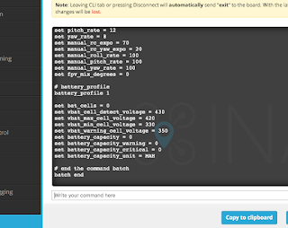 Your entire setup can be seen by typing DUMP in the command entry space.
Or type DIFF to see just what has been changed.
You can save and share all this as a text file. Click Save to file.
All that text can be re-pasted into the "Write your command here" section for quick and easy setup of a new board.
There are many more commands and setup items available via the CLI than appear in the Configurator pages.
The Fixed Wing Wiki recommends a few extra settings that are not included in the previous pages. They need to be entered via the CLI.
Here are the extra setup commands I always add
set max_angle_inclination_rll = 600
set max_angle_inclination_pit = 600
(Increases the maximum pitch and roll angles to 60º for stabilised modes)
set small_angle = 180
(Allows the board to be armed at any angle)
set failsafe_throttle_low_delay = 0
(Prevents failsafe due to low throttle)
set inav_reset_home = FIRST_ARM
(Keeps the first arm position as home if the board disarms)
set nav_fw_allow_manual_thr_increase = ON
(Allows manual throttle above the cruise throttle setting)
INAV groups and videos for more information


 Which firmware target to flash?
 INAVFlight is Open Source firmware for flight control boards, which enables GPS navigation for planes and flying wings, as well as multi rotors.
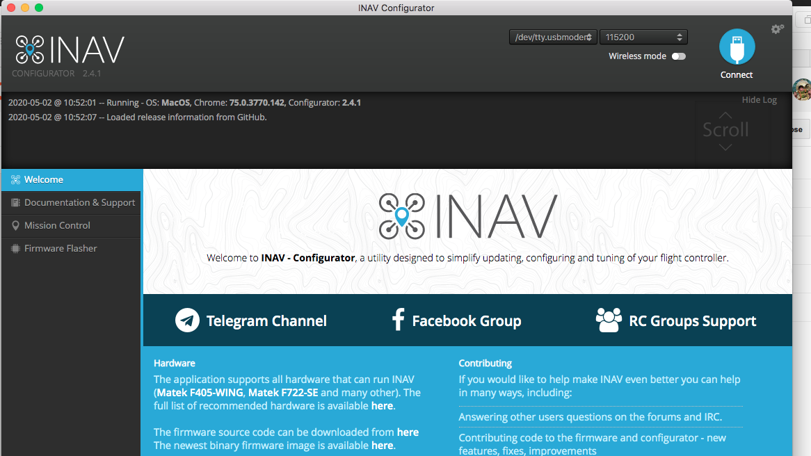 This is the computer program used to load and configure INAV firmware on your flight control board.
 Links to the required drivers can be found on the INAV Configurator front page.
 If the INAV firmware version and INAV configurator version are compatible then this is what you will see.
 Select the correct target for your board. The target may be written on the bottom of your board or on the product page.

 Check that channels are working as expected in this page.
 This is where you can configure The OSD to your liking. Add, remove and position items on the screen where you want them.
 Your entire setup can be seen by typing DUMP in the command entry space.