Some solutions are obvious and just require reading the manual, or checking connections. But some solutions are unexpected and weird.
This will document some of the more unusual problems that can mess up an RC setup
INAV
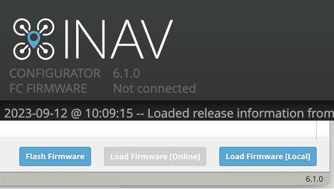
FIMI Manta VTOL won't connect to INAV Configurator after INAV 9 flash
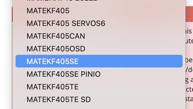
Cause - Use the wrong Firmware Target - Matek F405TE SD
Correct target for the Manta FC is Matek F405TE
Constant ESC beeping, Harware Failure and DSHOT Beeper Arming Flags.
Cause - GPS not enabled in INAV Configuration page
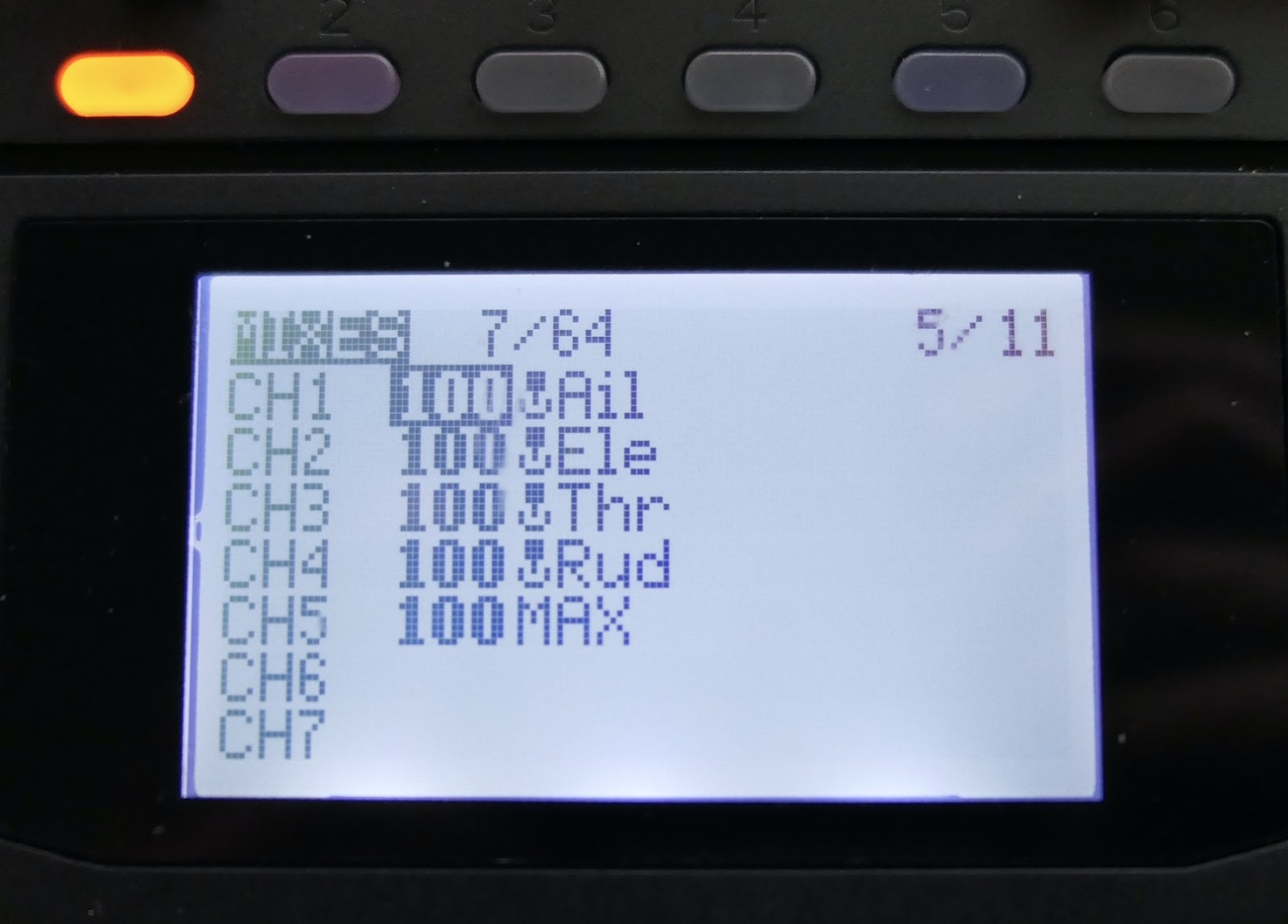
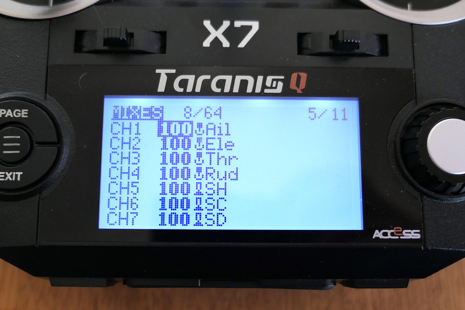
Cause 1 - Switch mistakenly assigned to Aileron channel in the radio
Cause 2 - Aileron or Elevator trim not centred
Cause 3 - Wrong Stick Mode selected eg. Mode 1 instead of Mode 2
Disarming with any aileron input
Cause - Used an existing model setup in the radio which had aileron mixing on the same channel as Arming in INAV.
GOLDEN RULE - Create a new fresh model for your INAV setup to avoid any leftover mixes
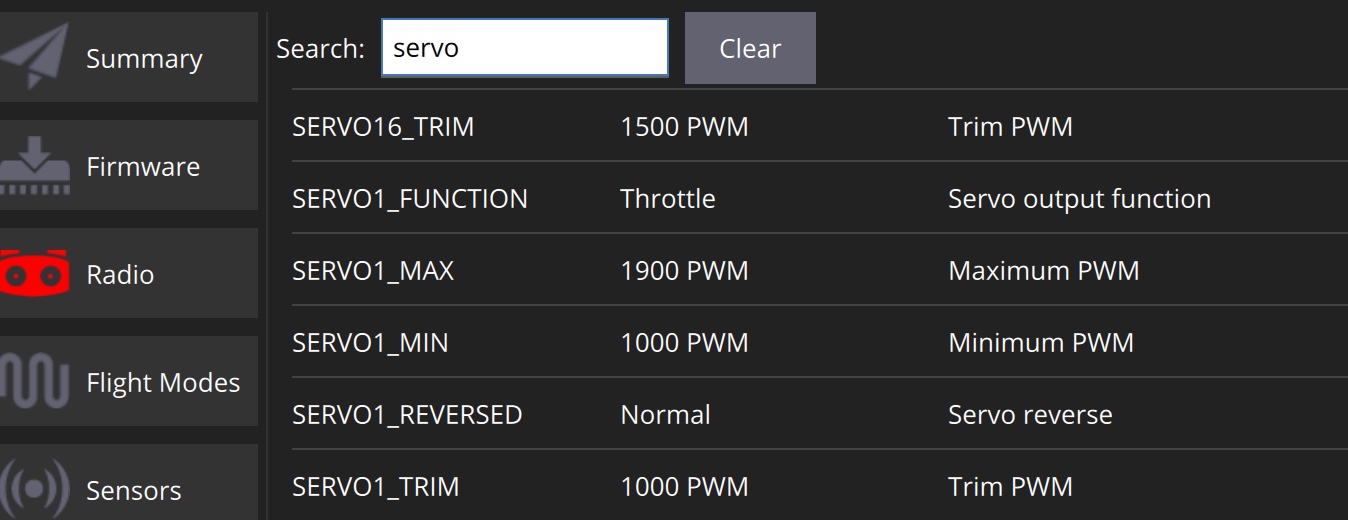
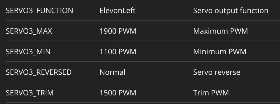
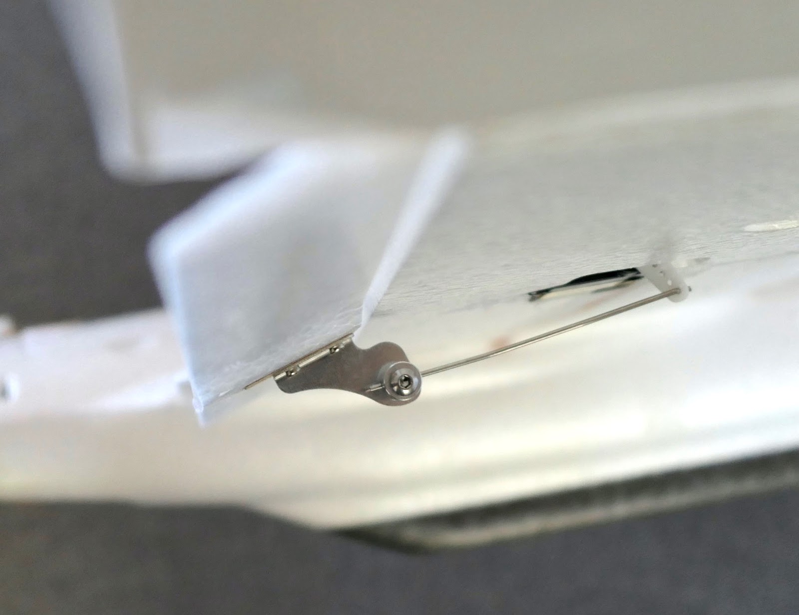
Outputs working in the INAV configurator but actual servos don't move
5V servos used with 6V servo BEC setting. One servo burned out and prevented others from working..
AtomRC Penguin on INAV
Turning right and crashing during launch.
Cause - ESCs were out of sync after lots of INAV VTOL configuration testing.
Recalibrating the ESCs in INAV Outputs Page corrected the problem.
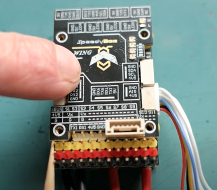
SpeedyBee F405-Wing MINI
USER modes not available for analog camera switching in INAV 7.0
Cause - This feature missed the deadline to be included in INAV 7.0. Updated firmware available on the Product page and INAV 7.1
Board stopped working after prolonged setup session
Cause - Bent pin on the "between-board" connector after repeated disassemblies.
Board not working at all
Cause - Wrong firmware flashed. The F405 Wing MINI uses the SPEEDYBEEF405WING firmware not the SPEEDYBEEF405MINI firmware
SpeedyBee F405-Wing
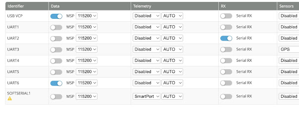
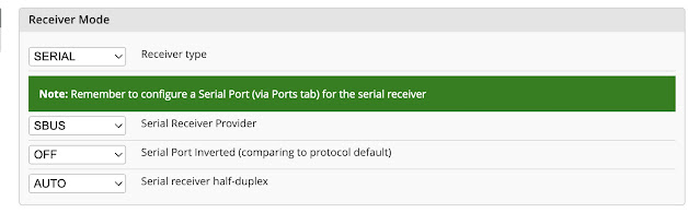
Graphs not moving in Configurator Receiver page, even with properly bound receiver.
Serial Rx was enabled for UART 1 and UART2 in the Ports page. Only one UART can be used for receiver connection.
No voltage on DJI 9V port
Cause - Bent ground pin needed straightening
No output on S8, no Soft Serial for S-Port function
Cause - Factory firmware bugs, upgrade to INAV 6.1.1
SIYI F24 INAV
Can't ARM
PWM end points and mid points are 1020 - 1540 - 2040 but INAV expects 1000 - 1500 - 2000
Solution - Adjust PWM values in the SIYI End Point page
FrSKY GRX8
Receiver unable to enter bind mode
Cause - Worn bind button contact. Needed to push harder on the bind button
Kootai A505 J3 Cub
Will not initiate
Cause - Futaba FASST protocol uses REVERSED throttle channel
Skywalker X8
Wings out of alignment.
Manufacturer glued the spar at the top of the channel in one wing and bottom of the channel in the other wing - Cut out spar and foam packing and re glue correctly.
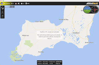
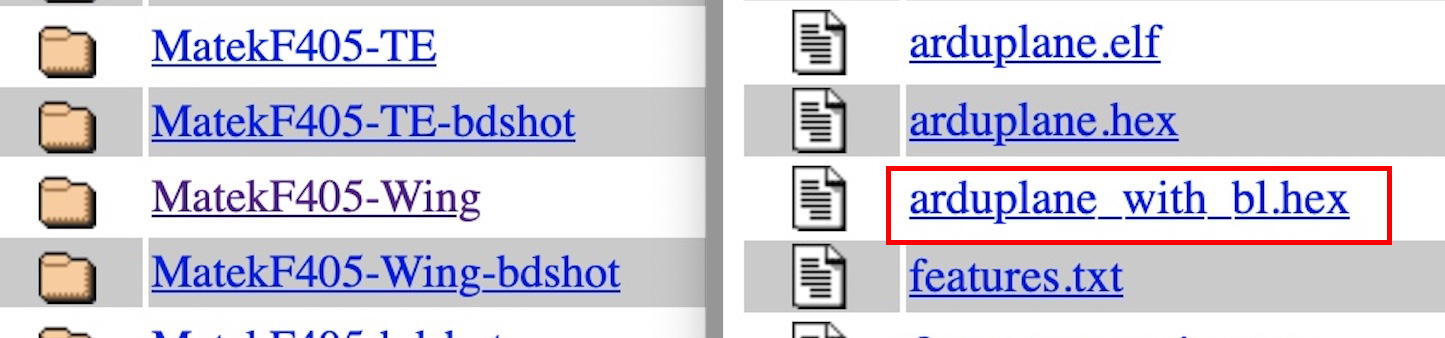
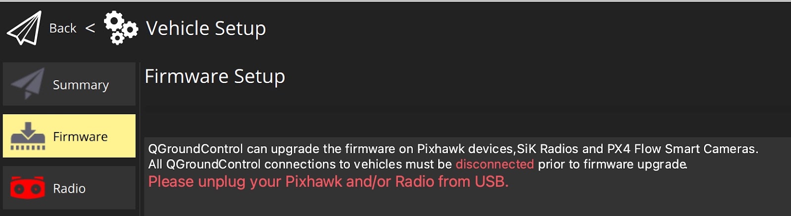
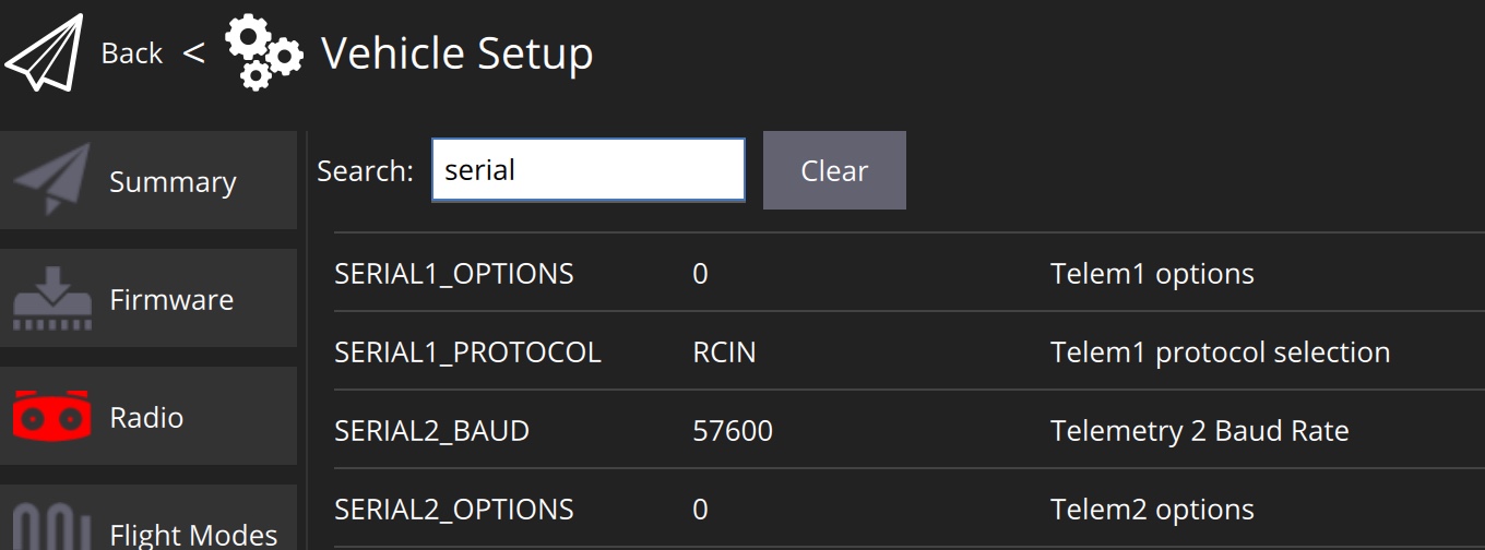
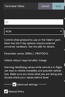
FIMI Manta - Matek F405 VTOL - Ardupilot ELRS
RC connection won't work
Cause - SERIAL5 was set to CRSF (Parameter = 23) as well as SERIAL6 which prevented Rx connection.
Only SERIAL6 should be set to CRSF
FLYSKY
FS-i6X radio - SBUS not working with FS-iA6B receiver but does work with FS-iA10B
Cause - Unknown. Possibly early FS-iA6B firmware does not include SBUS
SBUS can be used for connection to INAV FCs giving automatic Failsafe operation.
When using iBUS the failsafe must be set in the radio to switch Mode channel to INAV Failsafe Mode