
My gear for this ArduPilot test:
Matek F405-Wing board, LTE Rambler Wing, RadioMaster Boxer, ELRS receiver and RF module.
QGroundControl for Mac
All of this information comes from the ArduPilot Plane documentation - https://ardupilot.org/plane/index.html
Initial firmware flashing with INAV
Connect the board to INAV Configurator in DFU mode by holding the DFU button while connecting the USB
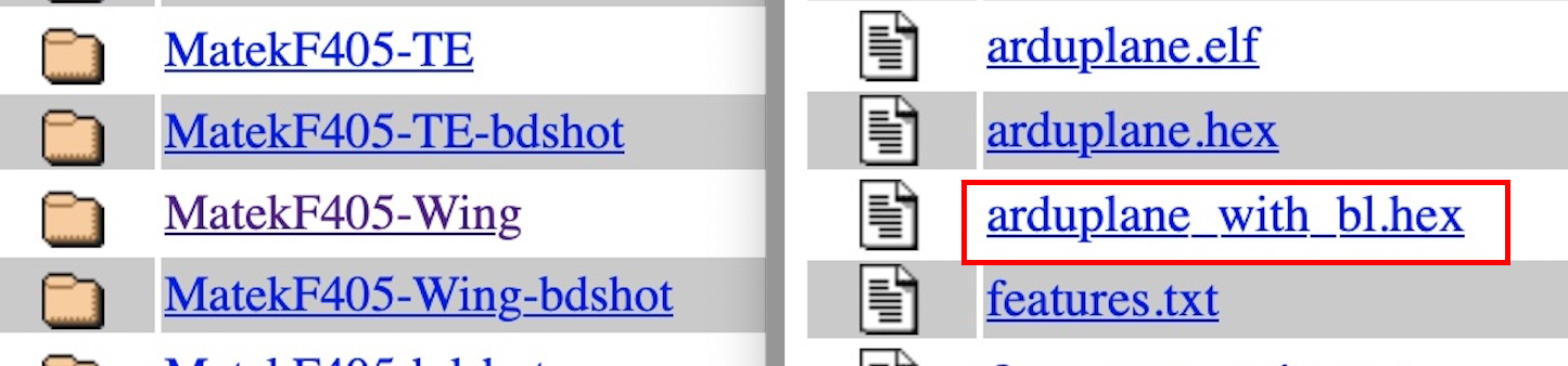
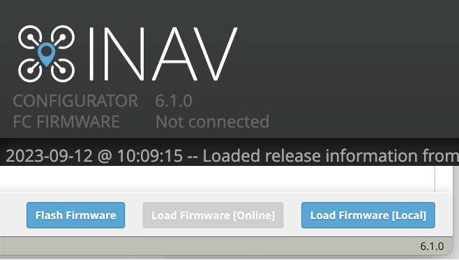
Select Firmware Flasher then Load Firmware (Local)
Locate the dowloaded arduplane_with_bl.hex file and select Flash Firmware
Once Ardupilot firmware is flashed to the board QGroundControl can be used for updates and configuring.
Configuration with QGroundControl
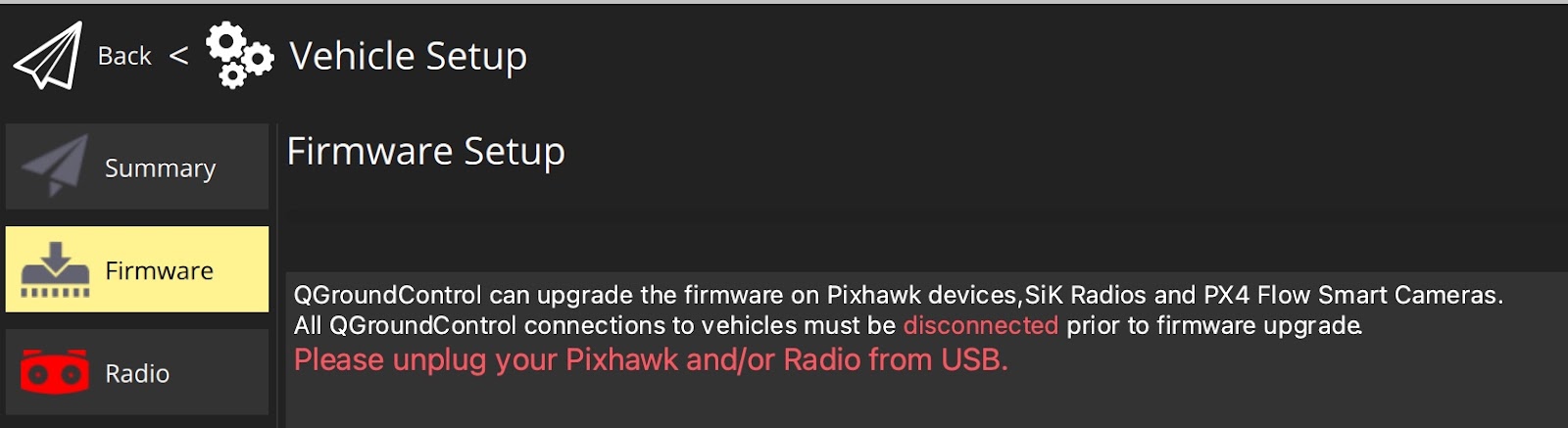
Open QGroundControl and connect the F405-Wing via USB
Parameters screen should appear in a few seconds.
Calibrate Accelerometer
Set up the ArduPilot model in your radio.
Model setup for ArduPilot must have no mixing, no rates or expo. No matter what style of plane you are configuring, this is how the mixing page on your radio should be.
All control surface mixing and channel reversing is done in QGroundControl
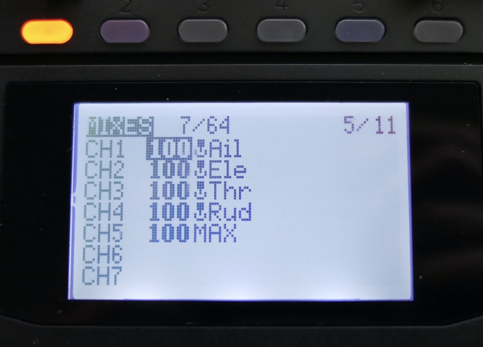
Ch 1 100% AIL
Ch 2 100% ELE
Ch 3 100% THR
Ch 4 100% RUD
Ch 5 100% MAX (ELRS requirement)
All ArduPilot's Flight Modes are on Ch 8 by default
Ch 8 100% SC for 3 positions operating 3 Modes
OR
Mixing for 6 modes using combination of SC (3 pos) and SD (2 pos) switches
Ch 8 31% SC -45% Offset, SD Up
ADD 31% SC +45% Offset, SD Down
OR
Ch 8 65% S3 (6 position switch)
Weight of 65% is required so the 6 PWM values match the ArduPilot Mode PWM ranges
Make sure the receiver is bound to the radio
Parameter Setup
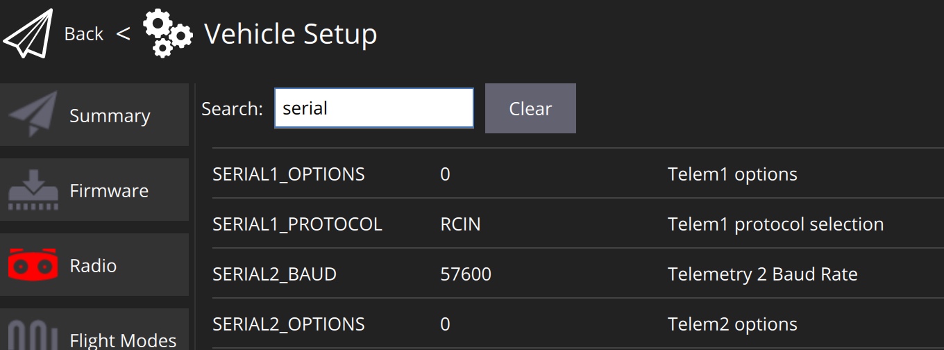
Configuring SERIAL inputs (UARTS)
Note that some FCBs have a different UART numbering sequence to the Ardupilot SERIAL numbering. Check the board's product page or the Ardupilot board info list. https://ardupilot.org/plane/docs/common-autopilots.html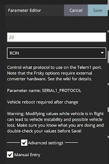
SERIAL3_PROTOCOL - GPS
Baud Rate is automatically adjusted
No other SERIAL inputs need to be changed at this stage (Unless you have HD FPV that needs UART connection)
Connect ELRS receiver RX and TX to UART1 on the board. Connect receiver power to 4.5V pin if you want it to be powered from USB for setup
Calibrate Radio in QGroundControl
With the receiver connected and bound to the radio, click on the Radio tab.
Follow the prompts while moving sticks and switches to calibrate Ardupilot for the radio.
This configures the stick functions or RC inputs, and sets the channel endpoints
Configuring motor and servo connections
SERVOn_FUNCTION
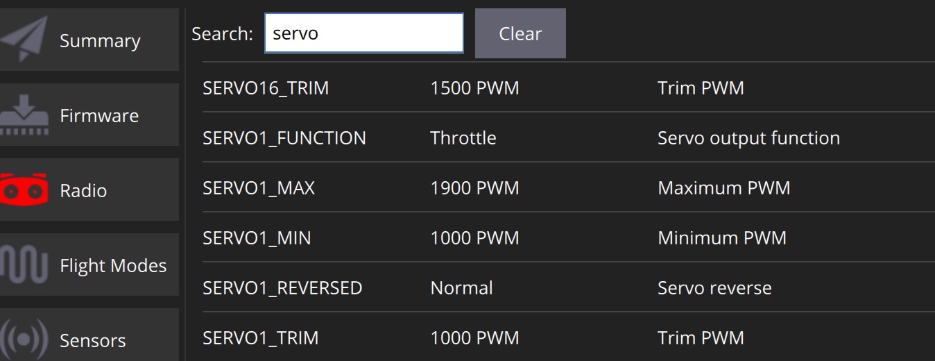
Change SERVO1_MIN to 1000
ESC signal connects to S1 pins on the F405
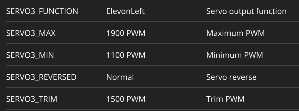
Change SERVO3_TRIM to 1500
Left Elevon connects to S3 pins on the F405
Configuring other parameters
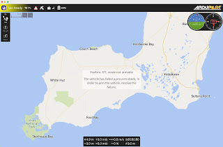
SAFETY (Click the Safety tab)
Safety Checks - Leave ALL ticked.
Return To Launch Altitude - Change if desired. I use 7000cm (70m)
COMPASS_ENABLE - Disable
Otherwise Safety Checks will prevent arming
ARSPD_TYPE - None
Otherwise Safety Checks will prevent arming
ARMING_RUDDER - ArmorDisarm
To allow arm and disarm with rudder stick.
Arming by a Switch is also available
FS_LONG_ACTN - RTL
Return to Launch on a "longer than short" Failsafe.
Short Failsafe Action is preset to CIRCLE to attempt RC reconnection, then reverts to Long failsafe after 2 sec.
SERVO_AUTO_TRIM - Enable
Continuously trim servo midpoints for level flight in Manual
TRIM_PITCH_CD - 300
300 centi degrees for 3º of nose up for level flight (maintain altitude) in FBWA. Adjust for your craft
TRIM_THROTTLE - 38
For criuse throttle of 38%. Adjust for your craft
RSSI_TYPE - ReveiverProtocol
Allows ELRS RSSI and LQ to be displayed correctly
Configuring Control surface movements
1. Correct stabilisation directions
IMPORTANT - Do this before step 2.
Check control surface movements for stabilisation in FBWA Mode
Without touching the sticks -
Left elevon should move up and right elevon down, when the left wing is raised
Right elevon should move up and left elevon down, when the right wing is raised
Both elevons should move up when the tail is raised
I needed to make the following changes to give correct stabilisation elevon movements
SERVO3_FUNCTION - Change to ElevonRight
SERVO3_REVERSE - Change to Reverse
SERVO4_FUNCTION - Change to ElevonLeft
2. Correct stick input directions
Check control surface movement for stick inputs in Manual Mode
My elevator action was reversed, so I needed reverse the elevator input (RC2) in parameters
RC2_REVERSED - Reverse
Coming from INAV I prefer to reverse RC inputs in QGroundControl and not in the radio. But I think either method is OK in Ardupilot.
Analog OSD Setup
Connect camera and video transmitter to the board
Search for OSD parameters
OSD_ENABLED - Enabled (To turn OSD on)
By editing the OSD parameters you can Enable and Disable OSD elements and position them by changing the X and Y parameters.
There are about 23 horizontal and 13 vertical positions
The F405-Wing board does not have enough memory to include alternative fonts.
However other fonts can be stored on the SD card and called up using the OSD1_FONT parameter
Download fonts from the Ardupilot Font repository
I changed to the INAV style font (font2.bin)
Copy the font2.bin file onto the SD card and choose OSD1_FONT = 2
Setup and maiden videos - https://www.youtube.com/@AndrewNewton/search?query=Ardupilot
No comments:
Post a Comment